Scripting commands and tools
The proposed scripting tools are optimized for efficient and flexible control of the (cryptographic) IP functions in simulation testbenches and hardware tests. They serve for sending 64-bit control words in control packets and n 128-bit data blocks in data packets and to receive 96-bit state words and m 128-bit data blocks defined in text scripts.
Two scripting tools are available:
- An interpreter included in the VHDL testbench file stimulating the design under test (DUT) during simulations
- A software interpreter script.exe running on the host PC and calling the corresponding hardware via USB
This way, the same scripts can be used in VHDL simulations and in hardware tests.
Contents
Input file syntax
The script lines start immediately in the first left column of the script page. There are three types of script lines:
- Comment lines
- Commands lines
- Data lines
Comment lines are not interpreted. There are four scripting commands: control, write only, read only and write and read command.
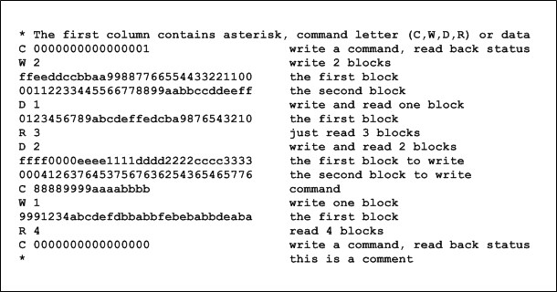
The next figure presents example of an input scipt file:
Comment lines
Lines starting with an asterisk represent comments. All characters in the line following the asterisk are ignored (as comments). Notice that comments can be added also in the second part of command and data lines (after the command and data block).
Command lines
Command lines can start only with one of the following letters: C, W, R or D.
Control command
The control command starts with the C character, followed by a space and a 64-bit control word written in hexadecimal. All characters after the 64-bit hexadecimal word are ignored (they can serve as comments). The hardware will respond to each control command with a 96-bit state word. Therefore, in order to read the current state of hardware, it is sufficient to send an “empty” (i.e. all zeros) command.
Write only command
The line with the write only command starts with the W character, followed by a space and a decimal number defining the number of 128-bit words that should be sent (written) to the hardware. All characters after the decimal number are ignored (they can serve as comments). The write only command line must be followed by the given number of 128-bit words written in hexadecimal. The hardware will not respond to the write only command.
Read only command
The line with the read only command starts with the R character, followed by a space and a decimal number defining the number of 128-bit words that should be received (read) from the hardware. All characters after the decimal number are ignored (they can serve as comments). The hardware will send in response to this command required number of 128-bit blocs in one data packet (maximum 120 words are allowed in the scripting file, while 64k words are supported by the hardware).
Write and read command
The line with the write and read command starts with the D character, followed by a space and a decimal number defining the number of 128-bit words that should be sent (written to the hardware) and received (read from the hardware). Number of sent and received blocks must be the same and thus only one decimal number should be given after the D character and the space. All characters after the decimal number are ignored (they can serve as comments). The hardware will send in response to this command required number of 128-bit blocs in one data packet (maximum 120 words are allowed in the scripting file, while 64k words are supported by the hardware).
Data lines
Data lines contain 128-bit data blocks written in hexadecimal. Data lines are allowed only after the write only and write and read commands. Number of succeeding data lines must correspond to the number of data blocks, which is given after the W and D commands. All characters after the first 128-bit data block of the line (32 hexadecimal characters) are ignored (they can serve as comments).
Output file syntax
Both software and testbench scripting tools create the log file containing the response of hardware or testbench to commands sent by the scripting tool. The log file can contain three types of lines:
- State lines
- Data line block prefix
- Data block lines
The next figure presents example of an output log file (which could be obtained as a response to the upper intput script file). The log file is created by the testbench or the script.exe tool (three state lines present in the log file were read in response to the transmission of three control packets, one in the beginning, one in the middle and one in the end of the transaction, and four 128-bits were received in one packed in response to the call of the “read only” or “write and read” command).
State lines
The state line in the log file starts with an S character followed by a space and a 96-bit state word written in hexadecimal. The state packet represents a response to the control packet sent to the hardware. The role of the state word is explained later at this page.
Data block prefix lines
The prefix of a block of data lines contains the 'D character followed by a space and a decimal value indicating the number of data lines that will follow. The prefix of the data lines block indicates that the hardware sent a data packet (containing a given number of 128-bit blocks) as a response of the read only or write and read command.
Data block lines
The data line in the log file contains a 128-bit data word written in hexadecimal. Number of data lines must correspond to the number given in the prefix of a data lines block.
VHDL testbench transactor containing the script file interpreter
In the Evariste II system, the host PC communicates with the target hardware via USB interface using packets. One of the main advantages of the Evariste II system is that the VHDL testbench uses the same script language (the same syntax) as the script file software interpreter described in the next section. It is therefore a good practice to use the same input script file in both VHDL testbenches and software calls of hardware functions using script interpreter software. The responses of both tools should be identical.
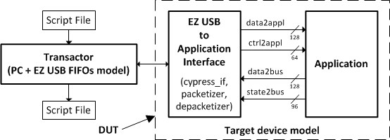
The structure of the VHDL testbench is depicted in the next figure. The VHDL testbench opens the input script file, interprets its lines and creates packets. The packets are then stored to the FIFO simulating the input FIFO of the USB interface controller. The target hardware model reads packets from the input FIFO, analyzes them in the depacketizer and sends them to the application just as in the real hardware (of course, the analog phenomena are not directly included in the simulation). The application VHDL model sends state and data words to the packetizer, which creates packets and saves them in the output FIFO. The testbench polls continuously this FIFO, reads and analyzes the packets present in the FIFO and creates the output log file using the same syntax as the script.exe software.
In the current version of the VHDL testbench, the input script file bus_script_in.txt is supposed to be placed in the Scripts_in directory and the testbench will create a log file bus_script_out.txt in the Scripts_out directory.
Script file interpreter software
The script file interpreter software script.exe is a Windows console 32-bit application using three command line parameters:
- Input filename
- Output filename
- Interface type
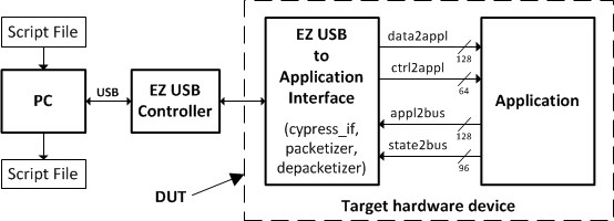
The software uses dedicated software driver (LabHC.sys) to access the target hardware and it acts as presented in the following figure. First, it reads the input script file, interprets the commands (lines) and creates packets. Then it sends packets to the target hardware via USB interface (using the driver). The target device reads packets from the USB interface controller FIFO, analyzes them in the depacketizer and sends commands and data to the application accordingly. The application sends state word and data blocks to the packetizer, which creates state and data packets and sends them to the host PC via the USB bus (the output FIFO of the USB interface controller). The script.exe software analyzes received packets and creates the log file. Input and output script files are placed in the same directory as the script.exe software. The exact structure of control, data and state packets is described later in this document.
Attention! The script.exe software is aimed at debugging of complex hardware systems and functions. Its main advantage is its flexibility: command and data packets can be created very easily. However, the script.exe software is not optimized for the speed. Once the data interface is debugged, the final software using the same commands as those used in the script file must be written. Furthermore, the number of 128-bit data blocks in one packet (the payload) is limited in the script.exe software to 120 blocks, but in hardware it is limited to 64k blocks!


