Software design
The Evariste III system software includes two kinds of communication software:
- a ready-made open source scripting
- a fast data acquisition software,
both interfacing the USB driver compatible with Windows XP and Windows 7-10.
For end user application, the designer can develop his application software based on software examples given in the system.
Contents
LabHC driver and its installation
The Evariste III system includes the USB driver compatible with Windows XP and Windows 7-10. Both 32-bit and 64-bit drivers are available. They are based on the original the GNU libUSB library and signed USB drivers. The driver installation is straightforward: once the motherboard containing the FPGA module is plugged into the PC, Windows recognizes the module as the LaHC Security Module and asks for the driver. The user should point to the directory containing the corresponding drivers (the directory "libusb-labhc").
Attention! The user MUST NOT launch the *.exe files, which are in this directory. He should just show the path to this directory, when Windows asks for drivers for the new device.
Remark: Compoared to the previous version, an additional switch /LibUSB was added to the software - it will say the program that it has to use the LibUSB driver.
Scripting software Script.exe
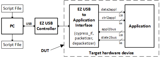
The proposed scripting tool is optimized for efficient and flexible control of the (cryptographic) IP functions. They serve for sending 64-bit control words in control packets and n 128-bit data blocks in data packets and to receive 96-bit state words and m 128-bit data blocks defined in text scripts. This software interpreter script.exe runs on the host PC and calls the corresponding hardware via USB.
The software Script.exe opens the script file given as the first argument of the command line. It then interprets the commands from the script file by creating packets and sending them to the bus/interface given as the third argument of the command (only USB bus is supported in the current version of the software). The software waits also for incoming packets arriving from the bus/interface, analyzes them and creates the log file having the name given as the second argument in the command line.
Example of the execution command: script.exe bus_script_in1.txt bus_script_out1.txt /USB
This command will launch script.exe that will read and interpret the file bus_script_in1.txt, send packets via USB bus and create log file called bus_script_out1.txt according to the received packets.
Input file syntax
The script lines start immediately in the first left column of the script page. They can contain:
- comments
- scripting commands
- data
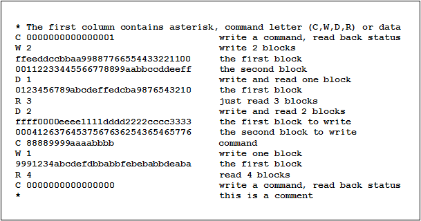
Following figure presents an example of a complete input script file:
Comment lines
Lines starting with an asterisk represent comments. All characters in the line following the asterisk are ignored (as comments). Notice that comments can be added also in the second part of command and data lines (after the command and data block).
Command lines
Command lines can start only with one of the following letters: C, W, R or D.
Control command
The control command starts with the C character, followed by a space and a 64-bit control word written in hexadecimal. All characters after the 64-bit hexadecimal word are ignored (they can serve as comments). The hardware will respond to each control command with a 96-bit state word. Therefore, in order to read the current state of hardware, it is sufficient to send an "empty" (i.e. all zeros) command.
Write only command
The line with the write only command starts with the W character, followed by a space and a decimal number defining the number of 128-bit words that should be sent (written) to the hardware. All characters after the decimal number are ignored (they can serve as comments). The write only command line must be followed by the given number of 128-bit words written in hexadecimal. The hardware will not respond to the write only command.
Read only command
The line with the read only command starts with the R character, followed by a space and a decimal number defining the number of 128-bit words that should be received (read) from the hardware. All characters after the decimal number are ignored (they can serve as comments). The hardware will send in response to this command required number of 128-bit blocs in one data packet (maximum 120 words are allowed in the scripting file, while 64k words are supported by the hardware).
Write and read command
The line with the write and read command starts with the D character, followed by a space and a decimal number defining the number of 128-bit words that should be sent (written to the hardware) and received (read from the hardware). Number of sent and received blocks must be the same and thus only one decimal number should be given after the D character and the space. All characters after the decimal number are ignored (they can serve as comments). The hardware will send in response to this command required number of 128-bit blocs in one data packet (maximum 120 words are allowed in the scripting file, while 64k words are supported by the hardware).
Data lines
Data lines contain 128-bit data blocks written in hexadecimal. Data lines are allowed only after the write only and write and read commands. Number of succeeding data lines must correspond to the number of data blocks, which is given after the W and D commands. All characters after the first 128-bit data block of the line (32 hexadecimal characters) are ignored (they can serve as comments).
Output file syntax
The scripting tool creates a log file containing the response of hardware to commands sent by the scripting tool. The log file can contain three types of lines:
- State lines
- Data block prefix line
- Data lines
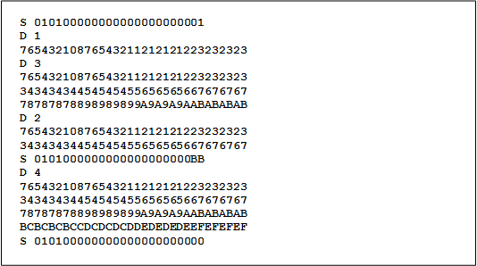
The next figure presents example of an output log file (which could be obtained as a response to the upper intput script file).
State lines
The state line in the log file starts with an S character followed by a space and a 96-bit state word written in hexadecimal. The state packet represents a response to the control packet sent to the hardware. The role of the state word is explained later at this page.
Data block prefix lines
The prefix of a block of data lines contains the 'D character followed by a space and a decimal value indicating the number of data lines that will follow. The prefix of the data lines block indicates that the hardware sent a data packet (containing a given number of 128-bit blocks) as a response of the read only or write and read command.
Data lines
The data line in the log file contains a 128-bit data word written in hexadecimal. Number of data lines must correspond to the number given in the prefix of a data lines block.
Attention! The script.exe software is aimed at debugging of complex hardware systems and functions. Its main advantage is its flexibility: command and data packets can be created very easily. However, the script.exe software is not optimized for the speed. Once the data interface is debugged, the final software using the same commands as those used in the script file must be written. Furthermore, the number of 128-bit data blocks in one packet (the payload) is limited in the script.exe software to 120 blocks, but in hardware it is limited to 64k blocks!
Example of an application software – fast data acquisition project
We give an example of simple application software aimed at fast data acquisition from FPGA modules (and namely random bitstream acquisition). Both source files and corresponding executable file are available. Using the source files, the user can very easily adapt the software to his needs.
The program DataACQ uses Cypress Application Programming Interface (API) for accessing the hardware via USB. It is a simple console application accepting several command line parameters. The program call has the following syntax:
DataACQ [file] [/H] [/?] [/LEN=xxx] [RND | RNDNOP] [/FILES=num]
- file – The name of the file that will be created
- /H – This argument will display the Help
- /? – Another way to display the Help
- /LEN=xxx – xxx is the length of the file in bytes in decimal (default 10000), e.g. LEN=125000
- RND or RNDNOP – This argument will determine the mode of the acquisition (in the context of random number generation):
- RND – mode of random number generation with post-processing (mode N°7)
- RNDNOP – mode of random number generation without post-processing (acquisition of the raw binary signal – the digital noise, mode N°3)
- /FILES=num – Determines number of files of length xxx that should be created (default value for xxx is 1). The software will generate automatically the names of files using random hexadecimal text streams.
Example:
DataACQ.exe /LEN=250000 /FILES=5
This program call will acquire data from the module and generate 5 files of 250.000 bytes. Besides creating the files, the program will display at the console window the following text for each created file:


