Simulation
In the Evariste III system, the host PC communicates with the target hardware via USB interface using packets. To help the designer in the development of the new system, we provide a VHDL testbench using the same script language (the same syntax) as the script file software interpreter described in the "Software design" section. It is therefore a good practice to use the same input script file in both VHDL testbenches and software calls of hardware functions using script interpreter software. The responses of both tools should be identical.
The VHDL testbench uses VHDL files and script input and output files. There are three testbench related VHDL files:
- the testbench VHDL file itself
- the FIFO module (simulating the behavior of the Cypress EZ USB input/output FIFOs)
- the VHDL package txt_util for the text output.
The top level VHDL testbench file instantiates the top level entity of the design under test (DUT), it opens and interprets the input script file, creates packets accordingly and sends them to the Cypress controller input FIFO model. It also polls continuously the Cypress controller output FIFO model for packets sent by the DUT. If the output FIFO is not empty, the testbench reads the FIFO data, analyzes packets and creates the log file accordingly.
Example projects from Section "Design examples" include two additional ModelSim *.do files: one for launching the simulation (the s file without extension) and the second one for defining the waveform window format. The user should just launch ModelSim, change the working directory inside ModelSim (File -> Change directory...) and type "do s" in the Transcript window. The simulator will then compile the project, open the waveform window, open the script files and write waveforms to the waveform windows and the log file to the output log file in the Sripts_out directory.
VHDL testbench transactor containing the script file interpreter
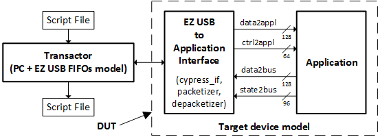
The structure of the VHDL testbench is depicted in the figure below. The VHDL testbench opens the input script file, interprets its lines and creates packets. The packets are then stored to the FIFO simulating the USB interface controller FIFO. The target hardware model reads packets from the input FIFO, analyzes them in the depacketizer and sends them to the application just as in the real hardware (off course, the analog phenomena are not directly included in the simulation). The application VHDL model sends state and data words to the packetizer, which creates packets and saves them in the output FIFO. The testbench polls continuously this FIFO, reads and analyzes the packets if they were present in the FIFO and creates the output log file using the same syntax as the script.exe software.
In the current version of the VHDL testbench, the input script file bus_script_in.txt is supposed to be placed in the Scripts_in directory and the testbench will create a log file bus_script_out.txt in the Scripts_out directory.
